Connector Types
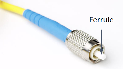
An optical fiber connector has a component called a ferrule, which encases the optical fiber. The end shape of this ferrule classifies it into the following four types.
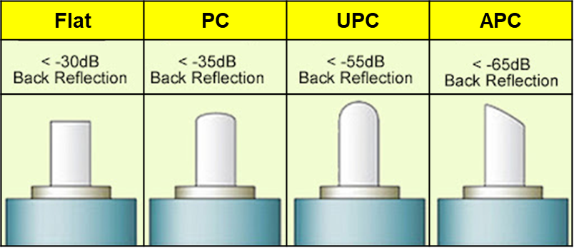
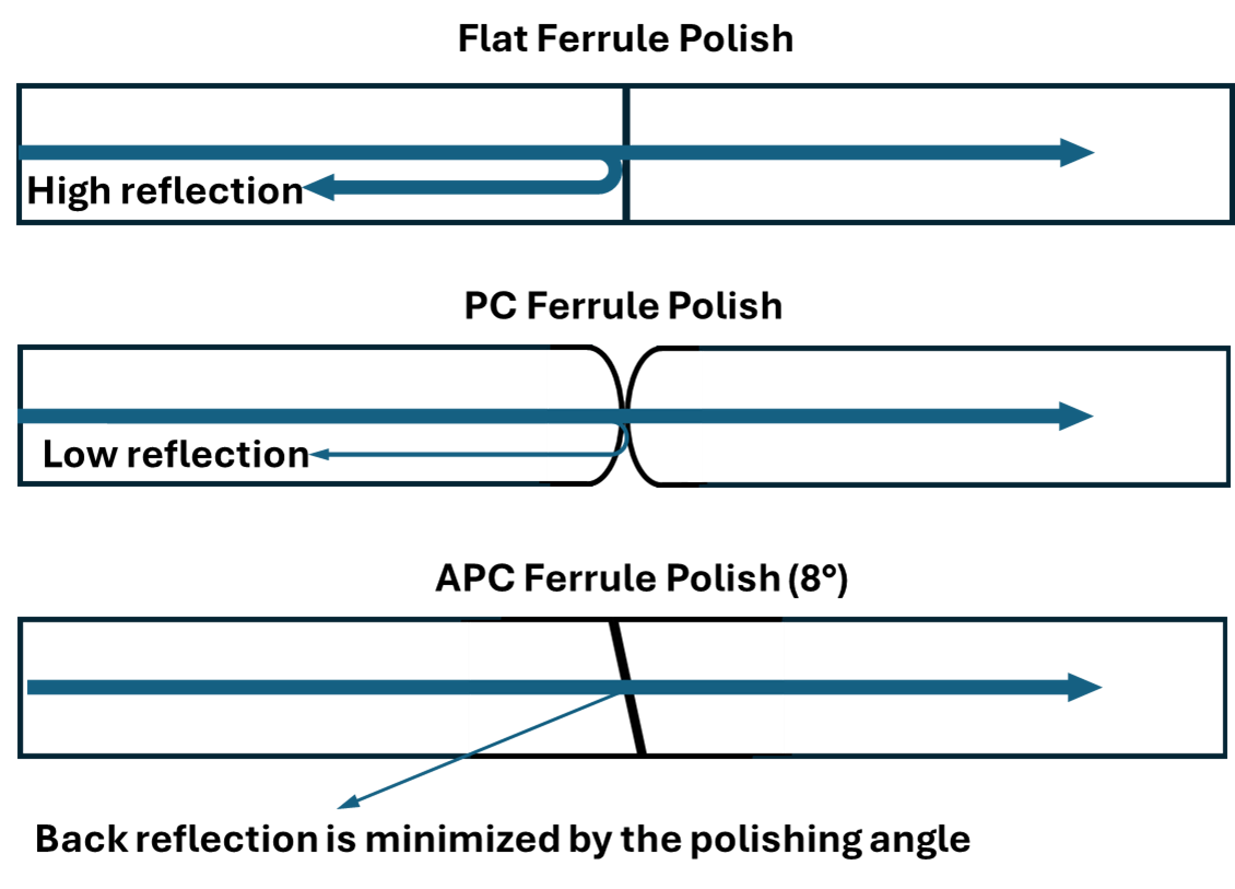
1. Flat Ferrule
The ferrule has a flat end face and is the simplest structure. Therefore, it is easy to manufacture and cost-effective. However, since the ferrules make contact in parallel without any angle, significant back reflection occurs, resulting in an insertion loss of about -30 dB or lower. It is sensitive to environmental changes, leading to high connection instability. It is mainly used for low-speed data transmission in general environments and may not be suitable for advanced applications.
2. PC (Physical Contact) Ferrule
The ferrule has a convex lens-shaped end face, which can reduce light reflection compared to a flat ferrule. As a result, the insertion loss is about -35 dB or lower, which is less than that of a flat ferrule, and the connection stability is excellent. However, it still has a relatively high reflection loss. It is widely used in general communication and data networks, providing a low cost and reasonable performance.
3. UPC (Ultra Physical Contact) Ferrule
The ferrule end face is processed more precisely than a PC ferrule, resulting in a wider contact area for the optical fiber and a smoother surface finish. As a result, the insertion loss and reflection loss are lower than -55 dB, enabling high-quality optical signal transmission. However, the complex manufacturing process due to the precision machining makes it relatively expensive. It is mainly used in high-quality optical communication systems such as high-speed data transmission, CATV, and FTTH.
4. APC (Angled Physical Contact) Ferrule
The ferrule end face is polished at an angle of 8 degrees, which adjusts the angle of light reflection to minimize reflection loss, resulting in approximately -65 dB or lower reflection loss. Therefore, it is suitable for equipment using laser light sources and is used in high-performance optical systems such as optical amplifiers. However, due to the specific angle of the polishing process, it is the most expensive compared to other ferrule types. It is primarily applied in high-output laser systems and other high-performance optical systems.
Having knowledge about the back reflection loss mentioned above can help in understanding the shape of the ferrule in connectors. Back reflection loss in optical connectors refers to the loss that occurs when optical signals are reflected at the junction surface of the connector and return to the light source. This phenomenon is similar to the principle of light reflecting off a mirror. Such reflections can degrade the performance of optical communication systems and are one of the main causes of damage to laser light sources.
The reasons for back reflection loss include imperfect alignment of the ferrule surfaces or incomplete contact due to dust or foreign substances between the ferrules, which can cause reflection. If the ferrule surface is scratched or has blemishes, light is scattered and reflected from the irregular surface. The greater the difference in refractive index between the optical fiber and the connector material, the more reflection occurs. If the angle of the ferrule surfaces does not match precisely, light is reflected in different directions.
Problems that can be caused by back reflection include: in the case of laser light sources, strongly back-reflected laser light can damage the laser source chip. Additionally, the reflected optical signal can interfere with the original signal, causing signal distortion, and the reflected signal can destabilize the laser resonator, degrading the performance of the entire system. Therefore, it reduces the signal-to-noise ratio (SNR) due to increased noise, thereby deteriorating communication quality.
To reduce back reflection loss, which causes such problems, the ferrule surfaces must be processed with high precision to enhance flatness and surface roughness. Before connecting the connectors, the ferrule surfaces should be cleaned to remove foreign substances, and the surfaces should be aligned accurately to maximize contact and eliminate any air gaps. Applying anti-reflective coatings to the ferrule surfaces can help reduce reflections. It is recommended to use APC (Angled Physical Contact) connectors, which can disperse reflected light in specific directions due to the polishing angle of the ferrule surface.
Finally, back reflection loss is measured using an OTDR (Optical Time Domain Reflectometer). The OTDR emits optical pulses and analyzes the reflected signals to measure reflection loss.
Comments
Post a Comment